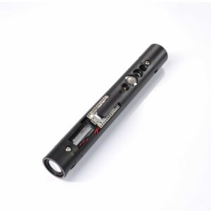
A lightsaber chassis is the internal frame that holds the soundboard, battery, speaker and switch so they cannot move inside the hilt. It is the part of a saber you never see and the part that decides whether a hard swing loosens a solder joint or does nothing at all.
Not every saber has one. Many entry-level hilts simply pack the electronics into the tube and let the wiring hold itself in place, which works until it does not.
A chassis is the difference between a saber you can open and service and one you replace when a wire breaks.
This page covers what a chassis holds, the difference between a full core and a battery sled, the print materials and why glass transition matters more than melting point, how fit and retention work, where rattle actually comes from, and how each design fails.
What’s on This Page
- What a Chassis Holds
- Why It Decides How Long a Saber Lasts
- Chassis Types: Core, Sled, Disc Stack
- Print Materials and the Heat Problem
- Fit, Tolerances, and Retention
- Laying Out the Core
- Rattle: What Is Normal and What Is a Fault
- Serviceability and the Upgrade Path
- How Chassis Fail
- Frequently Asked Questions
What a Chassis Holds
A chassis mounts five things: the soundboard, the battery cell, the speaker, the switch or switches, and the charging port. Everything else in the hilt is either the shell or the wiring that connects those five.
The reason the frame matters at all is that four of those five have to be held at fixed positions relative to each other.
The board needs to stay clear of the metal shell. The cell needs to stay reachable for charging and replacement. The speaker needs to sit against a vented end so its sound has somewhere to go. The switch needs to line up with the hole machined in the hilt.
None of that can be achieved by packing alone. A cell loose in a tube will slide into the board on the first hard swing, and the wiring between them takes the load.
| Component | What the chassis does for it | What goes wrong without one |
|---|---|---|
| Soundboard | Holds it at a fixed position clear of the shell | Board shifts and shorts against the hilt wall |
| Battery cell | Defines its position and keeps it swappable | Cell slides, harness flexes, solder joints crack |
| Speaker | Presses a 22 mm or 28 mm driver against the vented end | Speaker rattles and loses its seal against the vent |
| Switch | Aligns it to the machined hole in the hilt | Button sits off-centre and sticks |
| Recharge port | Pins it to the shell opening | Port pushes inward when the cable is inserted |
The correct installed state is a sealed metal tube with no loose mass in it. Every part that can move is a part that is wearing something down.
Why It Decides How Long a Saber Lasts
A chassis converts impact into structure instead of into wiring. When a saber is dropped or struck, the force has to go somewhere; with a frame, it goes through the frame into the hilt. Without one, it goes through the solder joints.
The failure is almost never dramatic. It is a wire that has been flexed a few thousand times at the point where it meets the board.
Stranded wire fails by fatigue at the stress point, not by overheating. A joint that moves a fraction of a millimetre on every swing accumulates that movement until the strands break one at a time, and the saber starts cutting out intermittently long before it stops working entirely.
The same logic applies to the battery contacts. A cell that shifts under its own weight will wear the contact surface and begin to oxidise, which shows up as an intermittent connection rather than an obvious break.
A frame removes the movement, and removing the movement removes the fatigue.
Chassis Types: Core, Sled, Disc Stack
There are three practical chassis designs: a full-length removable core, a battery sled that holds the cell only, and a disc stack built from separate plates on threaded rods. They differ in how much of the electronics they capture and how easily the build comes out of the hilt.
A full core is the most capable and the most work. It captures every component and slides out of the hilt as a single unit.
A sled captures the cell, and sometimes the speaker, leaving the board mounted to the hilt or to a separate bracket. It solves the most common source of rattle for far less printing and fitting.
A disc stack is the old approach and still a good one. Flat plates are spaced along two or four threaded rods, with each disc drilled or slotted for the parts it carries. A common spacing standard uses 4-40 threaded rod.
The board’s footprint is the constraint that sets the minimum bore. Common soundboards are roughly 72 mm by 24 mm, which is why a chassis designed around one board rarely accepts another without modification.
| Design | What it captures | Servicing | Typical use |
|---|---|---|---|
| Full removable core | Board, cell, speaker, switch, port | Whole core slides out as one unit | Sound builds, custom installs, upgrades |
| Battery sled | Cell, sometimes the speaker | Cell comes out; board stays in place | Simple builds, fixing a rattling cell |
| Disc stack | Depends on how many discs are used | Discs unbolt from the rods | Modular hilts, older builds, retrofits |
| Printed shell with pockets | Named parts only, model-specific | Varies; usually the whole insert | Hilts with a known internal layout |
| Battery holder, single | The cell only | Cell slides out the pommel end | Fits a 18650, 16650 or 21700 bore |
The design only works if it matches both the hilt and the board. A chassis modelled for one hilt’s internal diameter and switch spacing will not drop into another, which is why chassis are sold by hilt model rather than by size alone.
Print Materials and the Heat Problem
Chassis are almost always 3D printed, and the material choice is decided by glass transition temperature rather than melting point. PLA is the weakest choice here because it begins to soften near the temperature a bright LED can reach.
This is the point that catches people out. PLA does not melt inside a saber, and on that basis it looks fine.
But an LED module runs in the region of 85 °C in normal use, while PLA’s glass transition sits around 60 °C. Below the melting point but above the transition, PLA stops being rigid, and a part that is no longer rigid cannot hold anything in place.
PETG moves that transition to roughly 80 °C and is the practical default. Nylon is stronger again and tolerates around 90 °C, at the cost of shrinkage that needs trimming after printing. ABS sits higher still.
Approximate glass transition temperature by material. This is the temperature at which each material stops holding its shape, which is well below where each one melts.
Resin is a poor fit for a structural chassis. It is brittle under impact and has no useful advantage over the filaments above for this job, which is why it turns up in decorative parts such as a crystal chamber insert rather than in the frame.
Wall thickness matters as much as the material. Thin printed walls snap where a joining piece meets the body, and anything expected to take load wants at least a few millimetres of material at that joint.
Fit, Tolerances, and Retention
A printed chassis is held by three different mechanisms: a sliding fit against the hilt’s internal wall, a push fit between its own sections, and a retention screw that stops the whole assembly moving end to end. All three have to be right or the build rattles.
Printed parts rarely come out at exactly the modelled dimension, so the sliding fit is usually corrected by hand.
A fit that is too tight is sanded or deburred until the core slides without force. A fit that is too loose is built back up with tape on the section that meets the wall. Neither is a defect in the design; both are normal steps in an install.
Printed threads are the worst offender. A thread modelled at the nominal pitch often comes out tight enough to bind, and the problem gets worse in materials that shrink as they cool — which is exactly the trade-off for nylon’s higher heat tolerance.
The retention screw is what stops the core travelling. On many hilts it does double duty, anchoring the battery or the belt-clip wheel at the same time.
Where the mating faces are threaded, thread alignment matters more than torque. Cross-threading a pommel or coupler damages the thread on both sides, and a damaged thread cannot be fixed by tightening harder.
Separately, the screw that holds the blade in place should be tightened only about one rotation past the point where it touches the blade. Further than that deforms the blade wall, and the deformation is permanent.
Laying Out the Core
Laying out a core is a length-budget problem: the hilt has a fixed amount of internal room, and every component plus its wiring has to fit inside that room in an order that lets the build still be serviced.
Sketch the hilt outside first, then work inward. Mark where the switch hole sits, because the switch position is fixed by the shell and everything else has to reach it.
Two rules keep a layout workable. Leave enough travel for the core to pull out far enough to reach the memory card and the programming port without desoldering anything, and keep the wiring short enough that it never has to fold back on itself.
Route power and data separately. Power runs on heavier gauge wire, typically 22 AWG silicone, while data lines are thin, around 28 AWG. Running them together invites interference and makes the bundle harder to fold.
Standard bores and drivers set most of the dimensions: a 18650 cell is 18 mm across, a 21700 is 21 mm, and the common speaker sizes are 22 mm, 24 mm and 28 mm. A 1-inch blade socket is the other fixed number, because it decides the emitter end.
The shell sets where the switch and the blade socket are. Everything else is placed relative to them, and the chassis is what holds those positions.
Wiring length is the constraint that most often forces a redesign. A bundle that is too short prevents the core from coming out; one that is too long has to be folded somewhere, and folded wire is wire that eventually breaks.
Rattle: What Is Normal and What Is a Fault
Not all rattle is a fault. A motion sensor contains a moving element and a blade liner can knock inside the tube, and both are normal. Rattle from the battery, the board or the speaker is not, because those parts are supposed to be fixed.
The distinction is worth making because chasing a normal sound wastes a lot of time, and ignoring a real one damages the saber.
A cell that has room to move should be shimmed:
- Felt pads inside the pommel raise the cell until it seats against the chassis.
- An O-ring above the speaker or the cell takes up the remaining gap when the pommel is fitted.
- A retention screw, where the hilt has one, is the intended fix rather than a workaround.
A soundboard that has come loose from its mount is a different problem. Pressing it back against its adhesive surface and holding it for around half a minute restores the bond, but the underlying cause is usually that the board was never fixed to a chassis in the first place.
Blade wobble is its own case. Some play between the blade and the emitter is normal, and it can be reduced with a strip of tape around the base of the blade at the height of the retention screw indent.
Serviceability and the Upgrade Path
A chassis is what makes a saber upgradeable. If the core comes out, the board can be replaced without rebuilding the saber; if the electronics are packed into the shell directly, a board swap means an install from scratch.
This matters most for the upgrades people actually do, which are a soundboard change and a move from an in-hilt LED to a strip blade.
A board swap is a re-install, not a plug-in. Even where the wiring layout is similar between two boards, the harness has to be re-terminated and the new board fitted to the existing mounting.
The blade upgrade is the bigger fork. A board that drives a strip blade sends data through the blade connector to LEDs inside the blade, and a hollow blade has nothing to receive it — so the upgrade means a new board and a new blade.
Buying a hilt with a removable core up front is what keeps both of those options open. It costs more at the start and saves the whole build later.
Neopixel Lightsaber Soundboard Kit Proffie 2.2
Accessories / Neopixel Lightsabers
How Chassis Fail
Chassis fail in four ways: heat softens the printed material until it stops holding position, impact cracks a thin wall, a shifting part wears through a wire, and a stripped thread ends the build’s serviceability. Only the first is invisible.
Heat failure is the one that surprises people, because nothing looks burnt.
A chassis printed in a material whose glass transition sits below the LED module’s operating temperature will slowly lose its grip. The fit that was tight on assembly is loose a few months later, and the rattle that develops is the symptom rather than the cause.
Impact failure concentrates at joints. Thin printed walls and press-fit mating surfaces crack where the load changes direction, which is why wall thickness at the joint matters more than wall thickness overall.
The wiring failure is the slowest. A part that moves a fraction of a millimetre with every swing will eventually break the wire that connects it, and the break appears intermittent long before it appears permanent.
A stripped thread is the one failure that cannot be worked around. Once the pommel or coupler thread is damaged, the hilt’s serviceability is gone, which is why thread alignment is worth more care than tightening torque.
One number worth knowing before any of this: a soundboard, cell and speaker stack needs a continuous run of roughly 8 cm of clear internal length. Below that, the core has to shed a component rather than the hilt gaining room.
Frequently Asked Questions
Q1: What is a chassis in a lightsaber?
A: A chassis is the internal frame that mounts the soundboard, battery, speaker, switch and charging port inside the hilt. It holds each part at a fixed position so that impact goes through the frame rather than through the wiring. Not every saber has one, and the ones that do are the ones that can be opened and serviced.
Q2: Do I need a chassis?
A: Any build with a soundboard should have one. Free-wiring the components inside a metal tube leaves the battery and board free to move, and the wiring between them absorbs every swing. A chassis or sled is the part that stops that movement.
Q3: What material should a chassis be 3D printed in?
A: PETG is the practical default and Nylon is stronger again, tolerating around 90 °C. PLA is a poor choice for a structural part because its glass transition sits near 60 °C, which is below the operating temperature of an LED module. Melting point is not the number that matters here; glass transition is.
Q4: Why is my lightsaber rattling?
A: Work through the fixed parts first. A loose battery is the most common cause and is fixed with felt pads inside the pommel, an O-ring above the speaker, or a retention screw. A loose soundboard is the second. A motion sensor and blade liner can rattle normally, so rule out the first two before treating it as a fault.
Q5: What is the difference between a chassis and a sled?
A: A sled carries the battery and sometimes the speaker; a chassis carries the whole electronics stack. A sled fixes the most common source of rattle for far less work. A full chassis adds the board, switch and port, and can be pulled out of the hilt as a single unit.
Q6: Can I add a chassis to a saber that does not have one?
A: Sometimes. It depends on whether the hilt has enough internal room and whether a chassis exists for that specific hilt model. Chassis are modelled around one hilt’s internal diameter and switch spacing, so a design for another model will not drop in. Where no design exists, a disc stack built on threaded rods is the usual fallback.
Q7: How much internal space does a chassis need?
A: Assume the core needs a continuous run of roughly 8 cm for a standard board, cell and speaker stack, and more where a crystal chamber or a second cell is involved. The hilt also has to let the core travel out far enough to reach the memory card and programming port without desoldering anything.
Q8: What holds the chassis inside the hilt?
A: Three things: a sliding fit against the internal wall, a push fit between the chassis sections themselves, and a retention screw that stops the assembly moving end to end. The first two are usually corrected by hand with sanding or tape, because printed parts rarely come out at exactly the modelled dimension.
Q9: Does a chassis affect dueling?
A: It affects whether the saber survives it. Dueling is the case where impact forces are highest, and an unsecured cell or board will work its wiring loose over repeated hits. The chassis itself does not need to be rated for dueling; it needs to hold the parts that would otherwise move.
Q10: Why does my chassis get hot?
A: Heat comes from the LED module, not from the chassis. A white blade is every colour channel at once and is the highest-draw setting, so the emitter runs hottest in that mode. The fix is airflow and spacing between the heat source and any printed part, not a different chassis material.